

Abstract
Selecting the right gearbox and motor is critical for lifting equipment design. These components directly impact operational efficiency, stability, and total lifespan. Proper matching ensures safe and reliable performance under various working conditions. It also effectively reduces energy consumption and long-term maintenance costs. However, many users select components based only on experience or single parameters. This often leads to mismatched power levels or torque issues. This paper uses lifting capacity as the core starting point. We systematically analyze matching principles for gearbox and motor power. We also introduce key calculation methods and essential selection points. The study covers application scenarios for different types of lifting equipment. This helps users build a scientific approach to drive system selection. Ultimately, this improves overall equipment performance and economic value.
The gearbox and motor are the core of the lifting drive system. Their selection directly affects both equipment performance and operational safety. Improper selection leads to higher energy consumption and faster component wear. It may even cause serious safety risks during lifting tasks. Scientific matching based on lifting capacity ensures reasonable power output. This creates stable operations, increases efficiency, and extends service life.
Basic Components of the Lifting Drive System
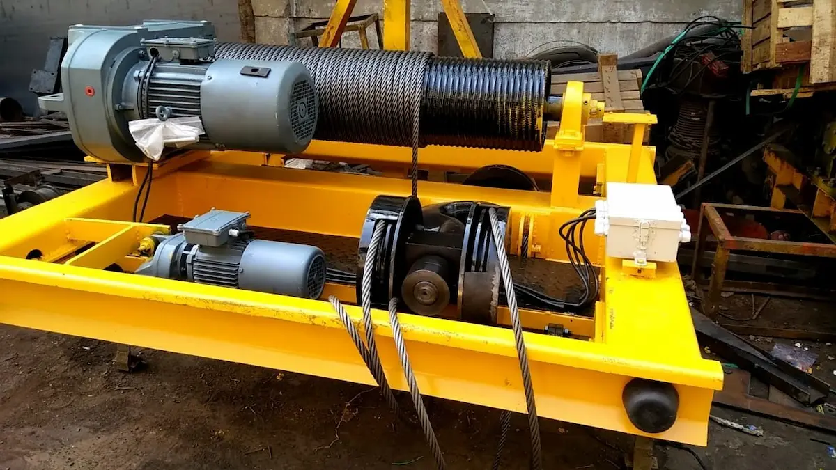
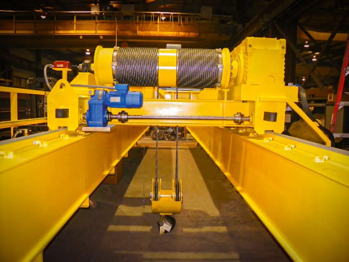
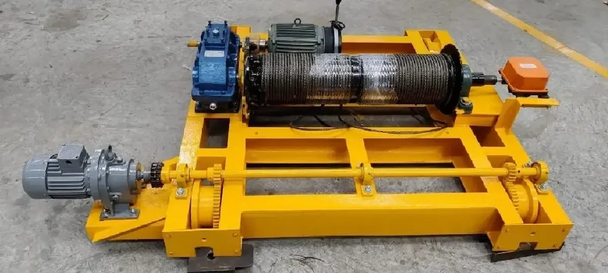
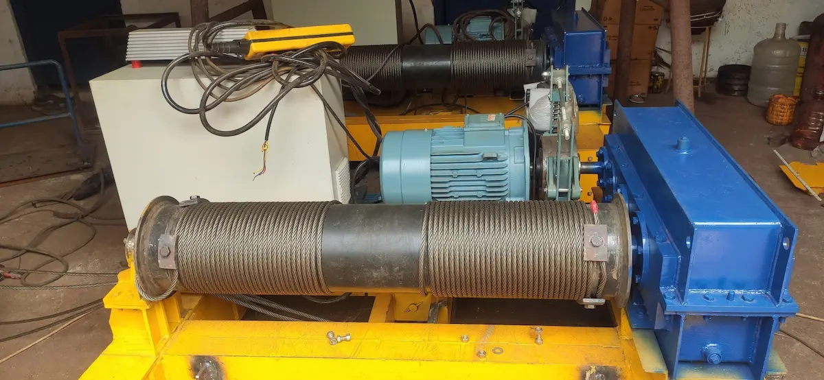
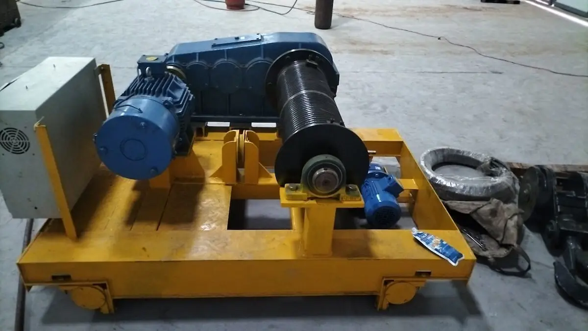
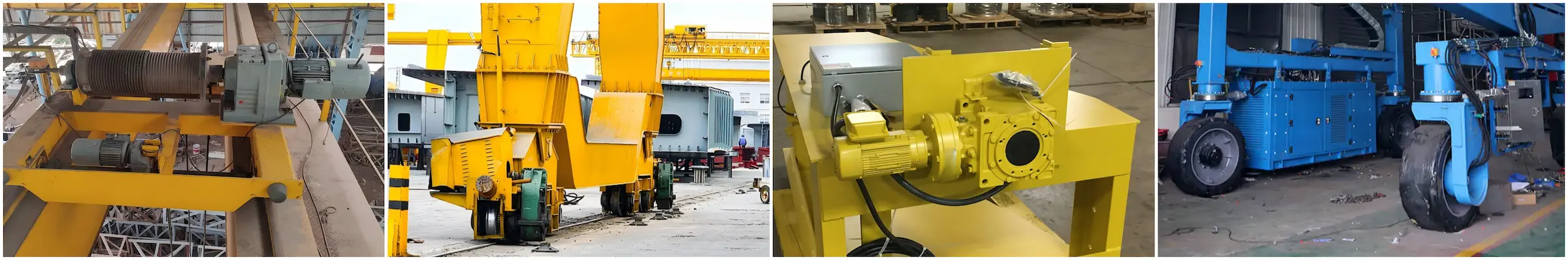
In lifting equipment, the drive system is the core module for lifting, moving, and positioning heavy loads. It primarily consists of two key components: the motor and the gearbox. By matching and working together, they efficiently convert electrical energy into stable mechanical power. This coordination meets the operational requirements of various working conditions.
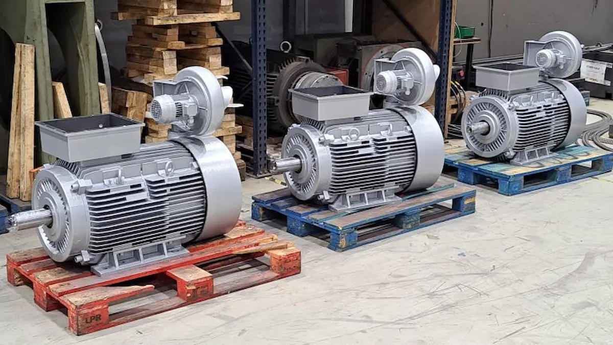
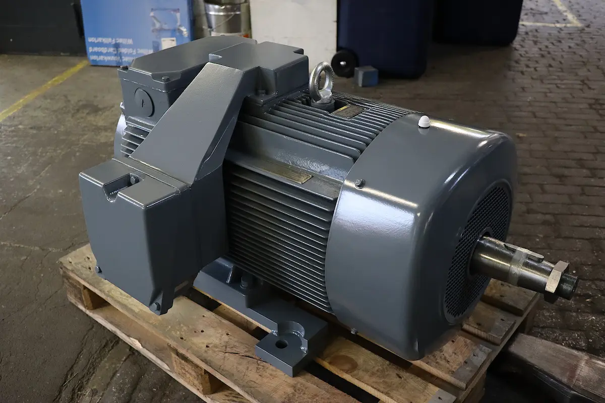
Role of the Motor (Providing Power)
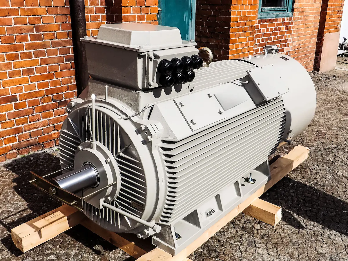
The motor is the power source of the lifting equipment. Its core function is to convert electrical energy into mechanical energy.
●Providing Primary Power: The motor generates high-speed rotating shaft power. This provides the initial driving force for lifting and traveling mechanisms.
●Speed Regulation and Control: In modern cranes, motors work with variable frequency drives (VFD). This ensures smooth starting, braking, and speed adjustment for stable lifting.
●High-Speed Characteristics: Industrial motors typically have high rated speeds (such as 960 rpm or 1440 rpm). This far exceeds the actual speed needed for lifting, requiring adjustment by subsequent mechanisms.
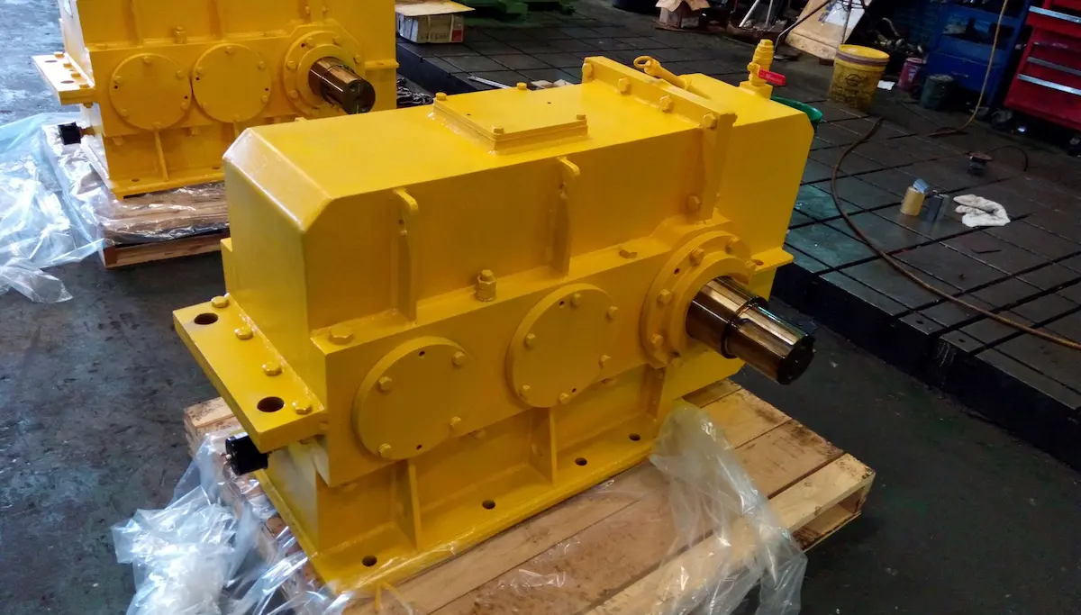
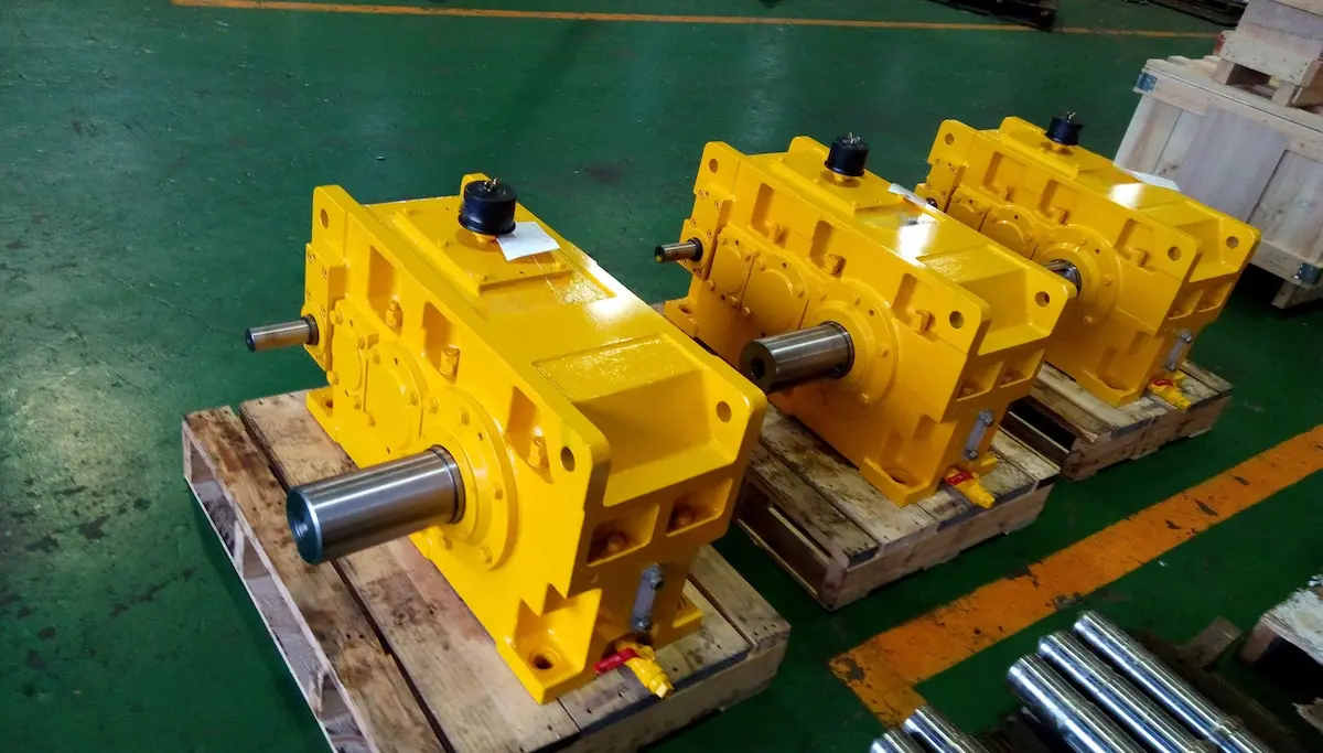
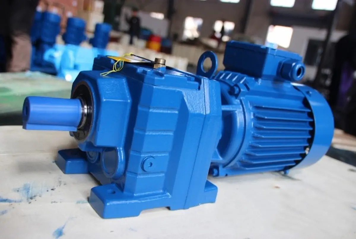
Role of the Gearbox (Reducing Speed and Increasing Torque)
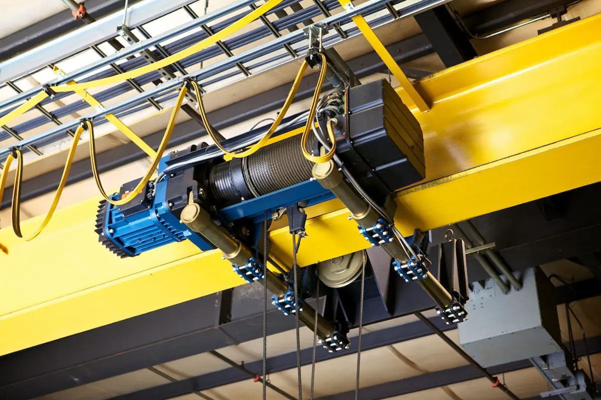
If the motor is the heart, the gearbox is the “muscle and joint” of the drive system. It performs two core functions through an internal precision gear transmission system:
●Reducing Speed: It reduces the high output speed of the motor to the actual working speed of the crane drum or wheels.
●Increasing Torque: According to the law of conservation of energy, torque increases as speed decreases for a given power level. The gearbox sacrifices speed to gain the massive torque needed to lift hundreds of tons.
●Support and Transmission: The gearbox acts as a bridge connecting the motor to the actuators (drums or wheels). it also supports radial and axial loads during movement.
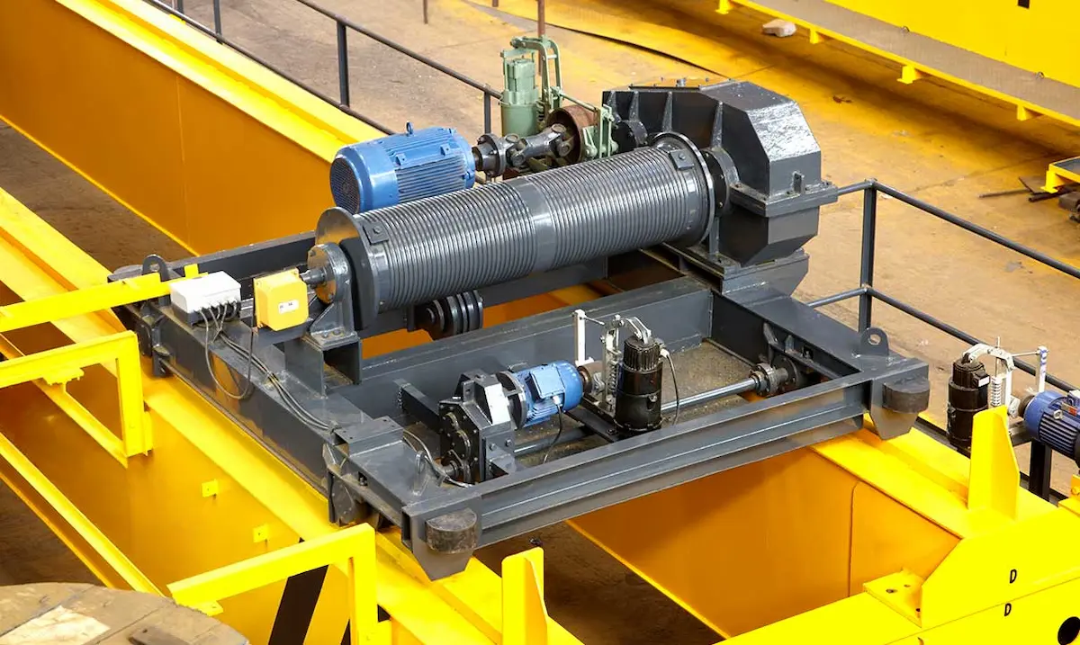
Principle of Coordinated Operation
The matching of the motor and gearbox follows strict physical formulas:

P is motor power (kW), T is output torque (N·m), n is speed (rpm), and η is transmission efficiency.
The working logic is as follows:
●Input side: The motor drives the gearbox at high speed n1 and low torque T1.
●Conversion process: The gearbox reduces speed through a specific gear ratio.
●Output side: The output shaft delivers low speed n2 (n2 = n1 / i). It also provides high torque T2 to drive the load.
This cooperation determines the crane’s load capacity. Improper matching may burn the motor due to insufficient torque. Or the gearbox may suffer gear failure from excessive instantaneous power. Therefore, scientific selection is essential for safe and efficient operation.
The Core Impact of Rated Load on Selection
In crane selection, rated load is the primary parameter for configuring the drive system. It directly affects motor power and gearbox torque selection. Only systematic analysis based on rated load ensures safe and efficient operation.
Relationship Between Rated Load and Load Force
Load force is the direct resistance the drive system must overcome. In hoisting mechanisms, it mainly comes from the weight of the load:
●Static load: The force when the load is stationary or moves at constant speed. The formula is  . The formula uses m as rated load and g as gravity acceleration.
●Dynamic load: Additional force generated by inertia during lifting start or acceleration. Larger rated loads create greater instantaneous impact on the drive system.
●Reeving effect: Wire rope reeving ratios (such as 2/1 or 4/1) redistribute load force. However, total power consumption still depends on rated load.
How Rated Load Affects Output Torque
Torque is the key indicator of whether a crane can lift a load. The gearbox output torque must exceed load torque for normal operation.
●Linear growth: Load torque T is proportional to rated load m. As tonnage increases, required drum torque rises linearly.
●Calculation logic:

(Where D is drum diameter, i is reduction ratio, and η is efficiency)
This means that if operating speed remains constant, doubling rated load nearly doubles gearbox torque demand. Therefore, high-tonnage cranes require gearboxes with larger center distance and higher gear strength.
Differences in Drive Requirements for Different Tonnage Equipment
Large changes in rated load fundamentally alter drive system design logic:
|
Rated Load Range |
Typical Equipment |
Drive Requirement Characteristics |
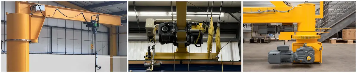
| Light duty (1t–5t) | Jib cranes, small electric hoists | Focus on flexibility and compactness. Integrated three-in-one drives are common, with small motor power and planetary or helical gearboxes. |
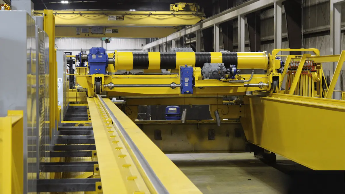
| Medium duty (10t–50t) | Standard overhead or gantry cranes | Focus on smooth operation and durability. Precise matching of hoisting speed and torque is required. Hardened gearboxes are typical, with variable frequency control to reduce inertia impact. |
| Heavy duty (100t and above) | Large gantry cranes, boat hoists | Focus on safety and redundancy. Multi-motor drives or dual gearbox parallel systems are common. Gearboxes must provide excellent heat dissipation and high gear fatigue strength. |
Rated load determines the lower limit of torque, while operating speed determines the upper limit of power. During selection, first ensure the gearbox withstands maximum static and impact loads based on rated load. Then determine motor rated power from the required hoisting speed.
Motor Power Calculation Method
In crane design, motor power is determined by precise physical calculations, not estimation. The following table summarizes key formulas and parameter definitions.
|
Dimension |
Description |
Notes / Physical Meaning |
| Basic calculation formula |  |
P: Required motor rated power (kW). m: Total rated load including lifting device (kg). G: Gravity acceleration (9.8 or 10 m/s²). |
| Hoisting speed (v) | Unit is usually meters per minute (m/min). Must be converted to meters per second (m/s) for calculation. | Power is proportional to speed. Doubling speed nearly doubles required motor power. |
| Total efficiency (η) | Includes gearbox transmission efficiency, drum efficiency, and pulley block efficiency. Typical range: 0.75–0.92. | Lower efficiency requires higher motor output to compensate internal friction losses. |
| Duty factor (Φ) | Determined by crane duty class (A3–A8). For example, FEM 2m (A5) corresponds to specific load spectra. | Considers heat and impact from frequent starting and braking on motor life. |
| Safety margin | Recommended range: 1.1–1.25. | Provides power reserve for voltage fluctuations, extreme environments, and 125% overload testing. |
Parameter Reference in Practical Selection
To prevent motor overheating and reduced lifespan, practical engineering follows this logic:
●Static power calculation: First calculate static power from rated load and rated speed.
●Dynamic correction: Cranes start and stop frequently, so duty cycle correction is required. For high duty classes like A7 or A8 grab cranes, use the upper safety margin.
●Environmental compensation: In environments above 40°C or at high altitude, motor cooling performance decreases. Additional power reserve or high-temperature motors are required.
Key Parameters for Gearbox Selection
If the motor determines the system’s power ceiling, the gearbox defines its load capacity floor. The following four dimensions ensure drive system reliability.
Determination of Rated Torque
Rated torque is the maximum torque the gearbox can safely transmit under specified conditions.
●Output torque calculation: The gearbox rated output torque T2 must exceed the actual load torque Tload.
●Starting torque consideration: At full-load startup, motor torque is typically 2–2.5 times rated torque. The gearbox must withstand this peak without gear failure.
●Formula reference: (fs is the safety factor, usually 1.5–2.5 based on crane duty class).
Gear Ratio Selection Principles
Gear ratio i connects motor speed nin and mechanism speed nout.
Matching formula: 
Selection logic:
●Speed balance: Excessive ratio reduces motor power but lowers efficiency. Too small a ratio causes excessive startup shock.
Multi-stage transmission: High-tonnage equipment usually uses two- or three-stage gearing for larger ratio coverage.
Impact of Duty Cycle and Usage Frequency
Gearbox fatigue strength is directly related to operating time.
●Duty class: Based on ISO or FEM standards. A8 cranes require much higher gear hardness, lubrication, and cooling than A3 cranes.
●Electrical duty (ED%): Frequent starts generate heat accumulation. High usage requires forced cooling or larger housings to prevent lubricant failure.
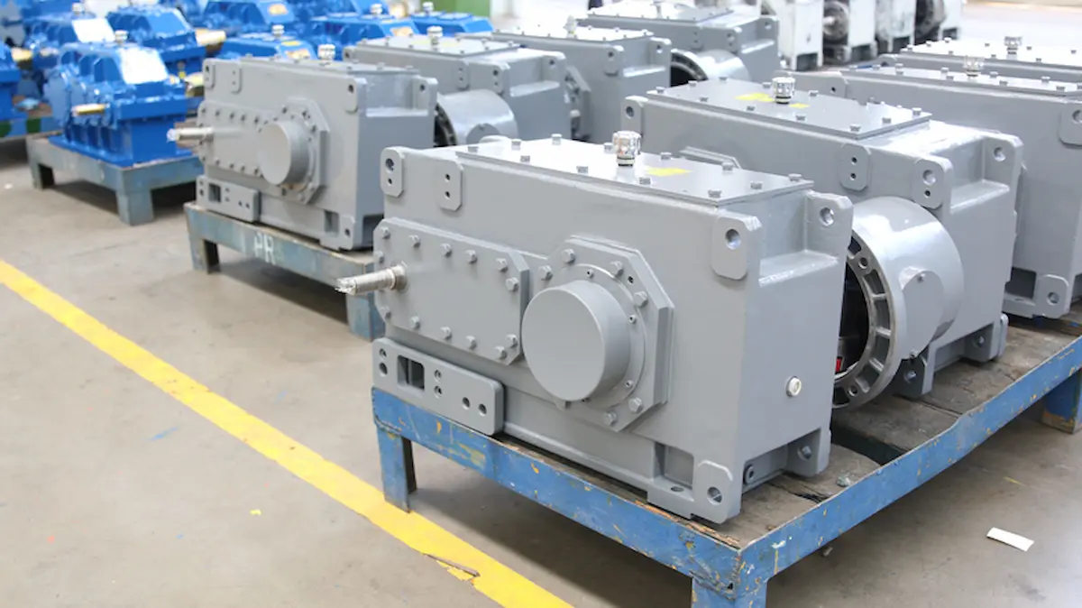
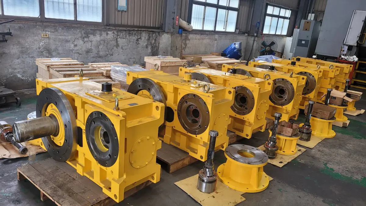
Comparison of Common Gearbox Types
Different gearbox structures affect installation space and transmission efficiency:
|
Gearbox Type |
Advantages |
Disadvantages |
Typical Applications |
| Hardened helical gearbox | High transmission efficiency, long service life, strong load capacity | Relatively large size and higher cost | Main hoisting mechanisms and crane travel drives |
| Planetary gearbox | Extremely compact structure, high power density, strong shock resistance | Complex structure and difficult maintenance | Electric hoists, compact boat hoists, port machinery |
| Cycloidal gearbox | Large reduction ratio, smooth operation, strong shock resistance | Lower efficiency and precision than helical gears | Jib crane slewing and medium or small travel mechanisms |
| Worm gearbox | Self-locking capability in some designs, very quiet operation | Low efficiency and high temperature rise | Small manual or low-speed auxiliary lifting equipment |
In HSCRANE projects, hardened helical gearboxes provide the best cost-performance and lowest failure rate. They balance high torque demand and frequent shock loads, making them the preferred choice for most B2B clients.
Motor and Gearbox Matching Principles
To ensure stable operation under frequent starts and heavy loads, three core principles must be followed.
Speed Matching
Motor high speed must be reduced to the required mechanism speed. An optimal range exists.
●Input speed limit: Motor rated speed (typically 1440 rpm or 960 rpm) must not exceed gearbox allowable input speed.
●Ratio selection: Ideal matching keeps the motor near rated speed for maximum efficiency. Avoid extremely large single-stage ratios; use multi-stage gearing for smooth transmission.
Torque Matching
In crane selection, torque is often more critical than power.
●Output torque verification: Gearbox rated output torque Tn must satisfy:

(Where Tload is actual load torque and K is a safety factor of 1.5–2.5).
●Starting torque capacity: The gearbox must withstand peak motor torque at startup without plastic gear deformation.
Power Redundancy Design
While precise matching is ideal, moderate redundancy improves safety.
●Thermal power verification: Continuous operation generates heat. Rated motor power should retain a 10%–15% margin after duty cycle correction.
●Overload capacity: Redundancy prevents motor winding overheating when lifting loads near rated capacity for extended periods.
Avoiding Underpowering vs. Over-specifying
In B2B projects, incorrect selection often swings between two extremes:
|
Phenomenon |
Manifestation |
Consequences |
| Underpowering the drive system (Undersized Motor) | Motor power is too small, or gearbox torque reserve is insufficient | Difficult startup, frequent motor overload trips, gear failure, and significantly reduced equipment life |
| Over-specifying (Oversized Motor) | Selecting excessively large drive power beyond actual needs | Cost surge due to high initial purchase price. Low efficiency from long-term light-load operation causing energy loss |
HSCRANE Matching Recommendations:
Adjust redundancy dynamically based on duty class (ISO M3–M8). High-frequency equipment should use higher margins. Low-frequency equipment should balance cost and performance.
Selection Suggestions by Crane Type
|
Equipment Type |
Core Application Scenario |
Motor Selection Focus |
Gearbox Configuration Recommendation |
Power Redundancy |
Selection Notes |
| Overhead crane | Indoor workshops, warehouses, assembly lines | Variable frequency motor (VFD). Focus on smooth startup and precise positioning | Hardened helical integrated three-in-one gearbox. High integration and low noise | 1.1–1.15 | Controlled indoor environment. Main concern is motor heating from frequent starts |
| Gantry crane | Outdoor yards, stockyards, port terminals | High protection motor (IP55+). Strong weather resistance and overload capacity | Helical-bevel gearbox with higher torque and heavy sealing against dust | 1.2–1.3 | Reserve additional power for wind load and track deformation |
| Jib crane | Fixed workstations, local lifting, machine support | Conical rotor motor or small VFD motor with electromagnetic brake | Cycloidal or worm gearbox for compact installation and frequent rotation | 1.05–1.1 | Space is limited. Power density and compact structure are priorities |
| Boat hoist equipment | Marinas, shipyards, offshore engineering | Marine corrosion-resistant motor with H-class insulation. Supports multi-point synchronization | Heavy-duty planetary or customized hardened gearbox with strong sealing | 1.25–1.4 | High-value loads with shifting centers require high safety factors |
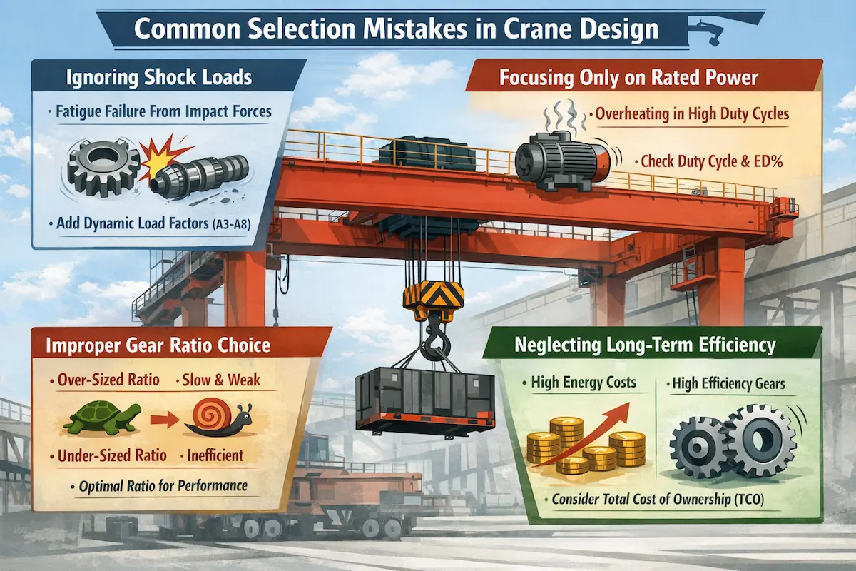
Common Selection Pitfalls
Ignoring Impact Loads
This is the most common mistake among inexperienced designers.
Phenomenon: Torque calculated only from steady lifting force, ignoring inertia at startup.
Consequence: Gear fatigue fracture from repeated overloads or coupling shear failure.
Countermeasure: Introduce dynamic load factors based on duty class. Increase factors for grab or magnet cranes.
Focusing Only on Rated Power
Rated power is static, while cranes operate dynamically.
Phenomenon: Selecting a 15 kW motor that can lift the load without checking duty cycle.
Consequence: Heat from frequent starts cannot dissipate, causing insulation aging or winding burnout.
Countermeasure: Verify using duty cycle such as S3-40%. Use higher insulation class motors for continuous duty.
Improper Gear Ratio Selection
Gear ratio directly affects motor operating range.
Phenomenon: Using very small motors with extremely large ratios, or the opposite.
Consequences:
●Too large ratio: Insufficient torque reserve, slow startup, low operating speed, reduced productivity.
●Too small ratio: Motor runs at low frequency or light load, causing poor power factor and energy waste.
Countermeasure: Select ratios that match rated motor speed with mechanism speed. Prefer standard ratios.
Ignoring Long-Term Efficiency
Selection based only on purchase price, not operating cost.
Phenomenon: Using low-efficiency worm gearboxes instead of high-efficiency hardened helical gearboxes.
Consequences:
●Energy costs increase significantly over time.
●Heat buildup accelerates lubricant degradation and component wear.
Countermeasure: Consider total cost of ownership (TCO). Efficient systems recover extra cost within 1–2 years.
HSCRANE Product Advantages
As a professional crane manufacturer, HSCRANE provides reliable and low-maintenance drive solutions for global B2B customers.
●Precise matching solutions: Based on FEM/ISO standards and digital modeling for optimal motor and gearbox pairing.
●High-efficiency design: Eliminates oversized motors and improves system efficiency by 15%–25% using VFD technology.
●High-quality gearboxes: Made from carburized alloy steel with hardened teeth for excellent shock resistance. Multiple seals prevent oil leakage. Service life exceeds 10 years.
●Multi-industry experience: Widely used in workshops, outdoor yards, and corrosive marine environments. Proven multi-point synchronization technology for boat hoists.
●One-stop solution: From digital modeling calculations to on-site commissioning, HSCRANE delivers turnkey drive systems tailored to your specific FEM/ISO duty class.
●Strong customization capability: Supports extreme lifting heights, high temperatures, explosion-proof environments, and special space constraints.
Scientific matching of motor power and gearbox is not simple formula stacking. It is a balance of safety, efficiency, and service life. Improper selection causes mechanical fatigue risks and long-term profit loss through energy waste and downtime.
For complex non-standard conditions or extreme lifting tasks, experience alone is insufficient. HSCRANE recommends professional engineering participation with digital modeling and full verification to keep systems within the optimal performance range.
Not sure about the exact gear ratio for your M8 heavy-duty crane?
Request a Free Drive Calculation Report from HSCRANE engineers within 24 hours.
HSCRANE has decades of experience in heavy machinery and marine lifting services. Whether planning a new project or upgrading equipment, our experts provide free drive configuration analysis and customized quotations.
[Click here to consult HSCRANE technical experts]
Further Reading: How to achieve precise control with powerful drive systems?
Matching the motor and gearbox ensures lifting capability, but precise stopping and holding are equally critical. The final key component is the crane brake selection.
Click the link below to learn more:
[Overhead Crane Brakes: Types, Working Principles & Application Scenarios Explained]
FAQ
Q1:How to calculate the motor power for an overhead crane?
A1:Add a 10-20% safety margin to the result to ensure reliability under voltage fluctuations and peak loads.
Q2:What is the ideal gear ratio for a heavy-duty gantry crane?
A2:Commonly 30:1 to 100:1. It must balance lifting speed with the massive output torque required to move heavy structures safely.
Q3:Why is duty cycle (ED%) important in crane motor selection?
A3:It defines the motor’s “run vs. rest” ratio. Choosing a low ED% for high-frequency tasks (A7/A8 class) leads to overheating and insulation failure.
This document is for reference only. Specific operations must strictly comply with local laws and regulations and equipment manuals.