

Overview
In crane hoist design, pulley block reeving ratio is rarely an isolated parameter. During project selection, we often meet this problem. After the ratio increases, single-rope pull falls. However, wire rope speed, drum rope capacity, pulley count, and drive matching all change. The pulley block reeving ratio affects lifting effort saving. It also directly affects wire rope, drum, pulley block, hook block, motor, and reducer configuration. Reasonably setting the ratio is important in crane hoist design and component configuration. This article covers ratio definition, parameter effects, key component configuration, and project cases. It helps readers clarify selection logic.
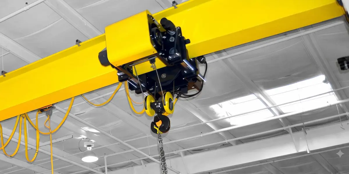
What Is the Crane Pulley Block Reeving Ratio? What Role Does It Play in a Crane Hoist?
Basic Definition of Pulley Block Reeving Ratio
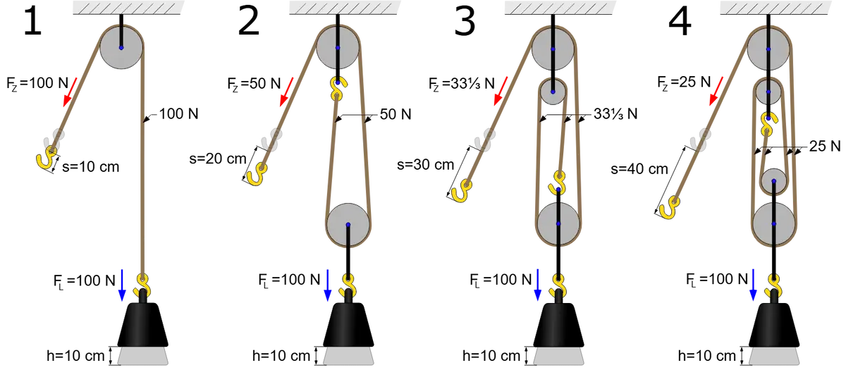
The pulley block reeving ratio is basically the ratio of rope falls to rope falls wound on the drum. In a double reeving pulley block, four rope falls carry the hook load and two rope falls enter the drum. Then the ratio is 4÷2=2. For a single reeving pulley block, the ratio equals the load-bearing fall count. For double reeving, it is half the load-bearing fall count. Common engineering ratios are 2, 4, 6, and 8. Bridge cranes most often use ratios 2 and 4.
The ratio first determines how much effort is saved. Ideally, ratio m equals lifting load divided by single-rope pull. It also equals rope linear speed divided by hook speed. Actual selection cannot consider only effort saving. The ratio is also a speed reduction factor. A higher ratio makes hook lifting speed slower. Many projects focus only on single-rope pull at scheme stage. They adjust later when full-load lifting speed misses productivity requirements. Costs are often high.
The key difference between single and multiple reeving is not whether lifting is possible. It is what cost is paid for lifting. Single or low-ratio pulley blocks have simple structure, fewer rope falls, and fewer pulleys. Wire rope bends less. They suit small and medium tonnage and speed-sensitive cases. Multiple-ratio pulley blocks use more falls to share load. Single-rope pull drops. However, pulley block layout becomes more compact and complex. Reeving and daily inspection workload rise. Ratio selection balances rope diameter and drum size against speed and structural simplicity.
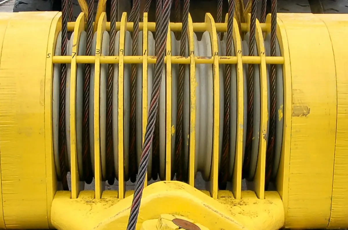
How Does Pulley Block Reeving Ratio Affect Crane Hoist Operation?
●Single-rope pull: As ratio rises, single wire rope pull usually falls. Do not simply divide load by fall count. Include pulley block efficiency; otherwise rope diameter may be selected wrongly.
●Rope speed and travel: Higher ratio increases wire rope travel distance and speed. At the same hook speed, the drum must rotate faster or hold more rope. This point is most easily ignored in scheme design.
●Layout and configuration: Different ratios require different pulley block layouts and component configurations. Reeving paths and hook block center of gravity change. It is not just adding more pulleys.
●Actual efficiency: Pulley bearing friction and wire rope bending losses reduce effort-saving effect. This becomes more obvious at higher ratios. Efficiency reduction and wear distribution should be reviewed together.
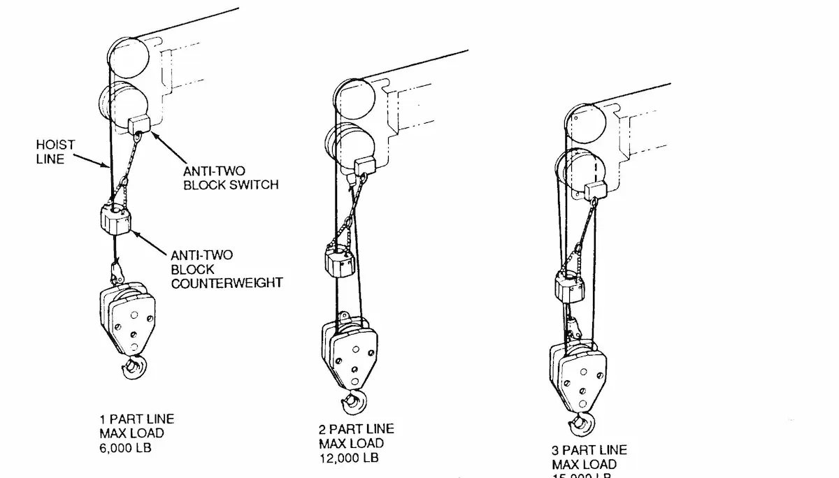
Relationship Between Pulley Block Reeving Ratio and Crane Hoist Design Parameters
The table compares parameter trends as ratio changes. It gives no standard answers. It shows trends only. Final values need project parameters and standards. Use it for direction, then calculate from working conditions.
|
Parameter |
Low ratio (m=2) |
High ratio (m=4–8) |
Selection note |
| Rated capacity | High single-rope pull; direct rope/drum load. | Lower single-rope pull; include pulley efficiency loss. | Hook block weight share rises. |
| Lifting speed | Faster hook at same drum speed. | Hook speed falls proportionally. | Check productivity and motor margin; VFD partly compensates. |
| Height / rope capacity | Small drum capacity. | Capacity rises with ratio; more drum length/layers. | Large height plus high ratio risks spooling/fleet angle. |
| Load-bearing falls | Fewer falls; simple reeving. | More falls; load uniformity depends on pulley accuracy. | Need rigidity and alignment. |
| Transmission efficiency | Usually 0.92–0.95. | Falls to about 0.85–0.90. | Do not use low-ratio efficiency for high-ratio power. |
| Duty class (FEM/ISO) | Low/medium intermittent duty suits low ratio. | High duty needs efficiency and wear checks. | Include maintenance and wear costs early. |
Practical Note on Speed and Rope Capacity: The key issue is not rope pull but speed–rope capacity interaction. Higher ratio raises rope speed and drum capacity. If height consumes drum length, only larger diameter or another ratio remains. Review height and speed together before setting ratio. This avoids late drum or fleet-angle changes.
Crane Hoist Design Support
When designing a crane hoist, pulley block reeving ratio selection directly affects key component configuration. HSCRANE can provide suitable crane hoist design schemes based on your rated capacity, lifting height, and working requirements.
[Contact us for professional selection advice]
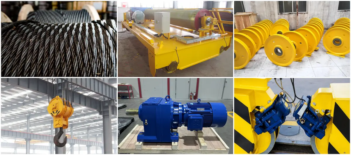
How Does Pulley Block Reeving Ratio Affect Key Component Configuration in a Crane Hoist?
●Wire rope — force: Higher ratio lowers single-rope pull; rope diameter may drop one size. Rope speed and bending cycles rise. Do not select rope by breaking force alone; check bending fatigue and grooves. High-ratio rope fails by bending, not breaking.
●Drum — capacity and parameters: Doubling ratio nearly doubles drum rope length at fixed height. Recheck drum length, layers, groove pitch, and fleet angle. Many schemes stall when drum length hits trolley frame. Adjusting ratio often beats drum changes.
●Pulley — count and layout: Low ratio may need one moving pulley group. High ratio needs more sheaves and longer reeving. Pulley diameter must match rope diameter. Do not shrink pulleys because rope diameter drops. Bending stress may rise.
●Hook block — design: Higher ratio adds moving sheaves to the hook block. Self-weight and center of gravity change. Heavier blocks need new motor and brake checks. Some retrofits ignored hook block weight. Empty hook lowering brake feel changed.
●Motor and reducer — drive: Ratio changes the pull-speed combination. Single-rope pull falls, but drum rope speed rises. Motor power cannot simply shrink by pull ratio. Match reduction ratio, drum speed, duty, and VFD range. High-ratio reducers often ignore high-speed margin.
●Brake and safety — conditions: Ratio affects drum torque, brake torque, and lowering frequency. High-ratio systems have more pulleys and lower efficiency. Heavy lowering brake conditions are complex. Recheck capacity, height, and overspeed setpoints by actual speed. Do not reuse low-ratio parameters.
What Are the Differences in Crane Hoist Component Configuration Under Different Pulley Block Ratios?
|
Configuration factor |
Lower ratio |
Higher ratio |
Easily ignored on site |
| Wire rope single-rope pull | Relatively larger | Relatively smaller | Do not use load ÷ fall count directly at high ratio. Include pulley efficiency loss. |
| Wire rope running speed | Relatively lower | Relatively higher | Higher rope speed makes fleet angle and drum groove wear more sensitive. |
| Total wire rope length | Relatively less | Relatively more | For large lifting height, rope capacity often limits before pull. |
| Pulley block structure | Relatively simple | Possibly more complex | More sheaves need better alignment and pulley block rigidity for load sharing. |
| Drum rope capacity | Relatively low | Usually higher | If drum length is limited by trolley frame, adjust ratio before adding layers. |
| Drive system | Designed for matching pull and speed | Must rematch pull, speed, and ratio | Motor power does not shrink with single-rope pull; check drum rope speed too. |
| Maintenance focus | Rope load and wear | Multi-pulley wear, reeving, and rope condition | High-ratio systems concentrate wear on rear pulley grooves. Cover full inspection path. |
We often use this table for internal scheme discussions. It is not a tool for setting ratio by lookup. In real projects, lifting height and user speed requirements often outweigh tonnage. The table helps judge direction. Specific values still need calculation by working conditions and standards.
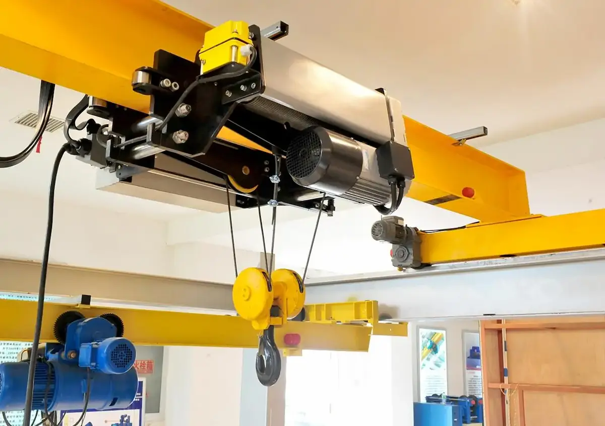
How to Achieve Reasonable Matching of Components in Crane Hoist Design?
1.Set basic parameters first: Confirm rated capacity, lifting height, lifting speed, duty class, and environment. This step looks basic, but many reworks start here. Users may give “common load” instead of rated capacity. They may omit speed control requirements. Unclear parameters make later ratio selection unreliable.
2.Calculate rope pull from load and ratio: Calculate single-rope pull with pulley block efficiency included. Select wire rope with the safety factor. Calculate several ratio options side by side. We often calculate ratio 2 and ratio 4 in separate rows. Compare rope diameter, drum size, and pulley size ranges. Then judge which option fits project limits better.
3.Complete drum and pulley block design: Define drum rope capacity, groove, fleet angle, and pulley diameter together. Layout must consider reeving path and hook block center of gravity. This step often creates “each part passes, assembly binds” problems. Check fleet angle and fixed pulley position in 3D layout. Do not wait until drawing release to change them.
4.Match drive and brake systems: Select motor and reducer by drum rope speed, efficiency, and load characteristics. Then check brake torque and thermal capacity. High-ratio systems have lower efficiency; keep reasonable motor power margin. Do not copy low-ratio configurations. For VFD lifting, check low-speed torque and braking sequence.
5.Check operation and safety performance: Review capacity limiter, height limit, overspeed protection, brake slip, and empty hook conditions. After ratio changes, adjust these protection setpoints. This final step is not a formality. Many site issues come from protection devices set with old ratio parameters. The crane hoist was fine, but interlock logic did not match.
HSCRANE Crane Hoist Design and Product Advantages
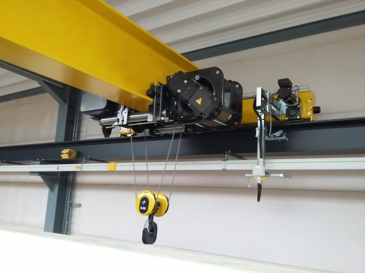
●Modular crane hoist design meets different ratio configurations: HSCRANE crane hoists use a modular architecture. Drum, pulley block, drive unit, and hook block are split by interfaces. Ratio changes do not require overturning the whole layout. Change pulley block configuration and drum rope capacity parameters. This logic follows ISO 4301-1:2016 classification of machine and mechanism duty. Adjusted mechanism class does not “hang in neutral.”
●FEM standard wire rope electric hoist meets different work intensities: FEM standard wire rope electric hoists use FEM 9.511:1986 duty rules for hoist service class. Light, medium, and heavy conditions use different ratio and component life combinations. One configuration is not forced onto all scenarios. For EU or European-standard projects, power-driven hoist safety follows EN 14492-2:2019 design, information, and testing clauses.
●Reasonable core component configuration improves crane hoist reliability: Wire rope, drum, pulley, and brake matching is not separate selection. They are checked as a load spectrum from lifting load, ratio, and rope speed. Structural design refers to EN 13001-1:2015 and EN 13001-2:2021 general principles and load clauses. Steel structure limit states follow EN 13001-3-1:2025 verification. This avoids “each part is enough, but the system binds.”
●Customized engineering design matches actual working environment: Vietnam projects have tropical high humidity. Guayaquil, Ecuador has coastal salt fog. Both directly affect ingress protection rating, coating system, and pulley block reeving path. Customization is not changing nameplates. It brings ratio, rope speed, and component configuration back to actual working conditions.
HSCRANE Crane Hoist Classic Project Cases
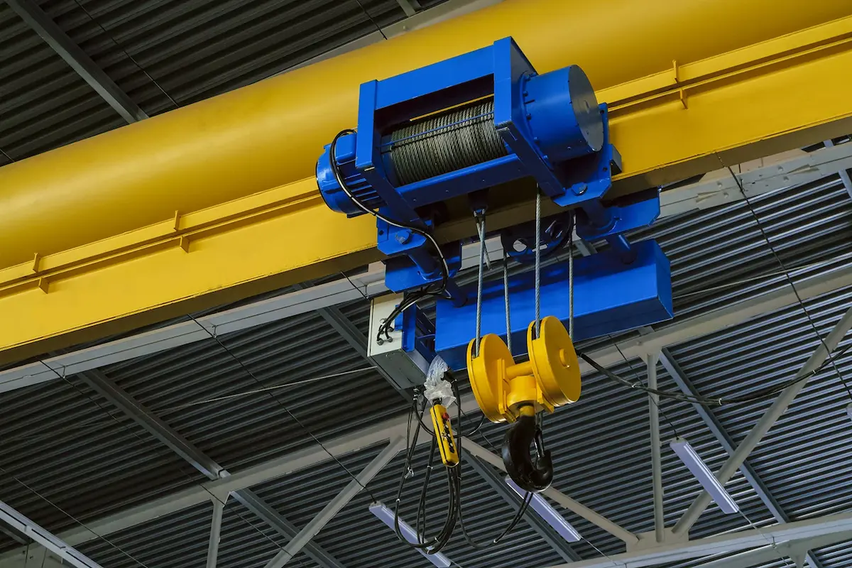
Case 1: Vietnam 5 t FEM Standard Wire Rope Electric Hoist Project
The client is a foreign-invested precision machinery manufacturer in Ho Chi Minh City. The new workshop has tight clearance and positioning accuracy requirements. It rejected traditional Japanese and local brands. It chose HSCRANE’s 5 t FEM standard low-headroom wire rope electric hoist. Core configuration: lifting height 9 m and VFD two-speed lifting speed 5.0/0.8 m/min. Duty class FEM 2m / ISO M5 and protection IP55. High-strength wire rope 2160 N/mm² and stepless VFD trolley travel. The Vietnam National Technical Safety Inspection Center witnessed the site test. Static load test used 1.25 times rated load (6.25 t). The load hovered 100 mm above ground for 10 minutes. The brake stayed closed during the test. Laser measurement after unloading found no permanent plastic deformation of the main girder. Acceptance passed on the first attempt. The C-type structure and push-type pulley block layout reduce hook-to-I-beam lower flange distance. Headroom is over 30% less than traditional hoists. The client gained nearly 1 m of vertical working space.
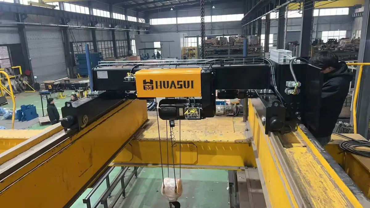
Case 2: Ecuador 30 t Double-Girder Overhead Crane Project
The client is in Guayaquil and makes large steel structures and hydropower components. It frequently lifts extra-long and extra-heavy parts. Traditional equipment lacked sufficient stability. The selected unit is a QD 30 t double-girder overhead crane. Main hook capacity is 30 t and span is 22.5 m, customized to building column spacing. Lifting height is 12 m and duty class is A5/M5. Power supply is 440 V/60 Hz/3 Ph. Main lifting speed is 3.5 m/min with VFD control. The box main girder was checked by finite element analysis. Full-load static deflection is controlled within L/700. Anti-corrosion uses epoxy zinc-rich primer plus polyurethane topcoat. Total film thickness exceeds 120 μm. Load tests used 125% static load (37.5 t) and 110% dynamic load. All data met requirements and the client accepted on site. After commissioning, component turning and transfer time dropped about 40%. Operating energy consumption fell about 15%.
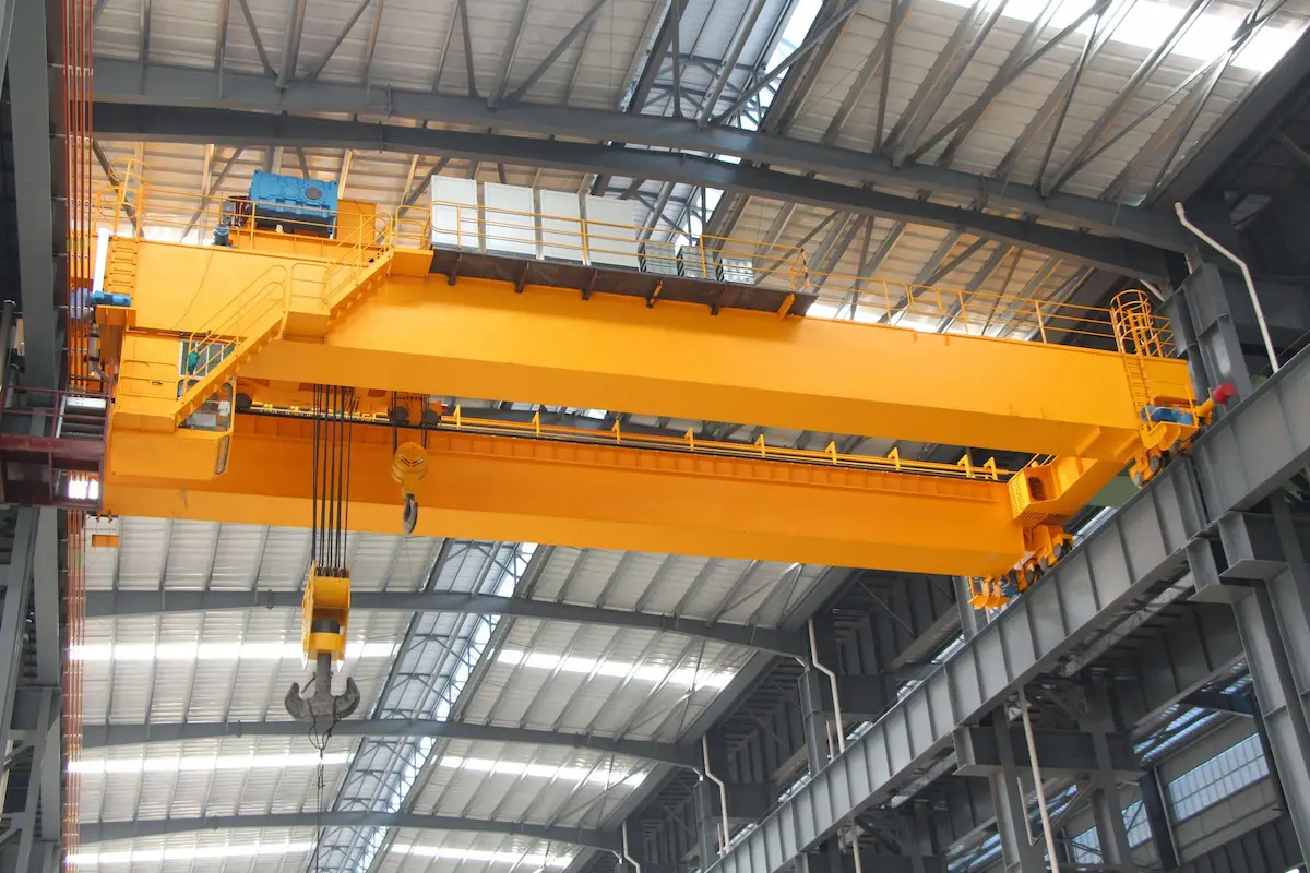
The Importance of Crane Hoist Configuration from Project Experience
·Different capacity and lifting height impose different crane hoist requirements: The Vietnam 5 t project has 9 m lifting height. A low ratio controls both rope capacity and headroom. The Ecuador 30 t project has 12 m lifting height. Its ratio and drum rope capacity matching logic is completely different. Copying the small-tonnage scheme would fail.
·Lifting speed and duty class affect motor and reducer selection: The Vietnam project uses FEM 2m / ISO M5 and two speeds 5.0/0.8 m/min. Motor and VFD are configured for precise low-speed positioning and higher frequency work. Ecuador uses A5/M5 and main lifting 3.5 m/min. Reducer and brake thermal capacity checks focus on heavy-load continuous cycles. The calculation method is not the same.
·Wire rope, pulley block, and drum must be matched as one system: Both projects verified one point. Single-rope pull being “sufficient” does not mean drum fleet angle and reeving path are acceptable. Low-headroom hoist pulley block compaction and bridge crane hook block conventional ratio layout follow different system matching paths.
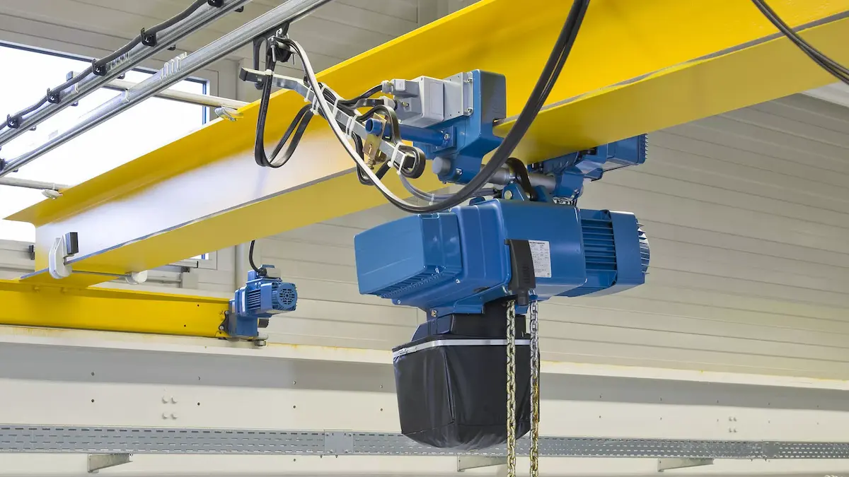
·Design by actual working conditions, not by simply increasing pulley block ratio: The Vietnam client needs headroom and inching positioning. A higher ratio is not always better. The Ecuador client needs heavy-load stability and corrosion durability. Higher ratio lowers single-rope pull but changes rope speed, rope capacity, and pulley wear. Real selection basis is always working condition limits, not the ratio number itself.
Conclusion
Let us return to the opening question: how should pulley block reeving ratio be set? Our view is direct. The ratio is not an isolated “larger or smaller” parameter. It is a chain linking wire rope pull, drum rope capacity, pulley block layout, and drive matching. A higher ratio lowers single-rope pull. However, rope speed rises, rope capacity rises, and pulley wear paths change. A lower ratio simplifies structure and raises efficiency. However, rope diameter and drum size may hit limits. The cases repeatedly verify one point. Working conditions come first, then ratio. System matching comes first, then part selection. If you decide only by effort-saving factor, later costs may be larger. These costs appear in drum spooling, hook block weight, or brake thermal capacity. Whether you are making a new scheme or reviewing existing configuration, put the ratio back. Put it into the whole crane hoist lifting chain.
Not sure which pulley block reeving ratio suits your lifting equipment?
Wire rope, drum, pulley, and drive system need integrated calculation for actual conditions. HSCRANE’s engineering team can analyze lifting parameters and match suitable equipment configuration. Welcome to submit your technical requirements for customized advice.
[Contact HSCRANE crane hoist engineers]
Further Reading:
The ratio is set, but the pulley diameter to wire rope diameter ratio must also be checked. An incorrect ratio brings bending stress and rope groove wear. Recommended reading: How to Match Crane Sheave Diameter to Wire Rope: Risks of an Incorrect Ratio.
【[Click to read →How to Match Crane Sheave Diameter to Wire Rope: Risks of an Incorrect Ratio】
FAQ
Q1: Is a higher pulley block reeving ratio always “safer”?
No. Higher ratio lowers single-rope pull. Safety does not come from stacking ratio. More pulleys mean longer reeving and higher alignment sensitivity. Rear-pulley groove wear often comes from poor matching. Low-ratio systems are safe with correct rope, spooling, and brake matching.
Q2: Can single-rope pull simply use “capacity ÷ fall count”?
No. Use F=Q/(N×η); η is total pulley block efficiency. Single pulley efficiency is 0.96–0.98. Series pulleys reduce total efficiency to 0.92–0.95 at ratio 2. At ratio 4 it is 0.85–0.90. Ignoring η makes rope diameter too small.
Q3: Does frequent wire breakage mean poor rope quality?
Not necessarily. Location and form matter more than count. Contact-side breaks often mean bending fatigue. Uniform breaks with wear flats suggest crushing. Check ratio when replacing rope. At ratio 2, a 10 t hoist shares 5 t per rope.
Q4: When should a lower ratio be preferred?
For large lifting height or limited drum rope space. Higher ratio nearly multiplies drum rope length. Rope capacity often limits before single-rope pull. High duty makes efficiency loss and pulley wear cumulative. Check drum and drive for larger single-rope pull.
Q5: How should FEM, ISO, and EN standards work together?
FEM 9.511:1986 sets mechanism service class by load spectrum. ISO 4301-1:2016 classifies machines and mechanisms generally. EN 14492-2:2019 covers power-driven hoist design and testing. EN 13001-3-1:2025 checks steel structure strength and fatigue. Set duty class first, then check components.
This document is for reference only. Specific operations must strictly comply with local laws and regulations and equipment manuals.