

Abstract
This article focuses on key design points of the overhead crane emergency stop system. It starts from industry safety background and national and international standards. The structure of the emergency stop system is systematically analyzed. Electrical control logic is also explained. Redundant circuit design and mechanical braking linkage are discussed. The implementation process from design to commissioning and site acceptance is described. Optimization strategies under complex conditions are also analyzed. Intelligent development trends are discussed. The goal is to improve response speed and operational reliability. The article also highlights HSCRANE’s advantages in safety control systems. Its customization capability is emphasized. This provides reference for building higher-level safety systems.
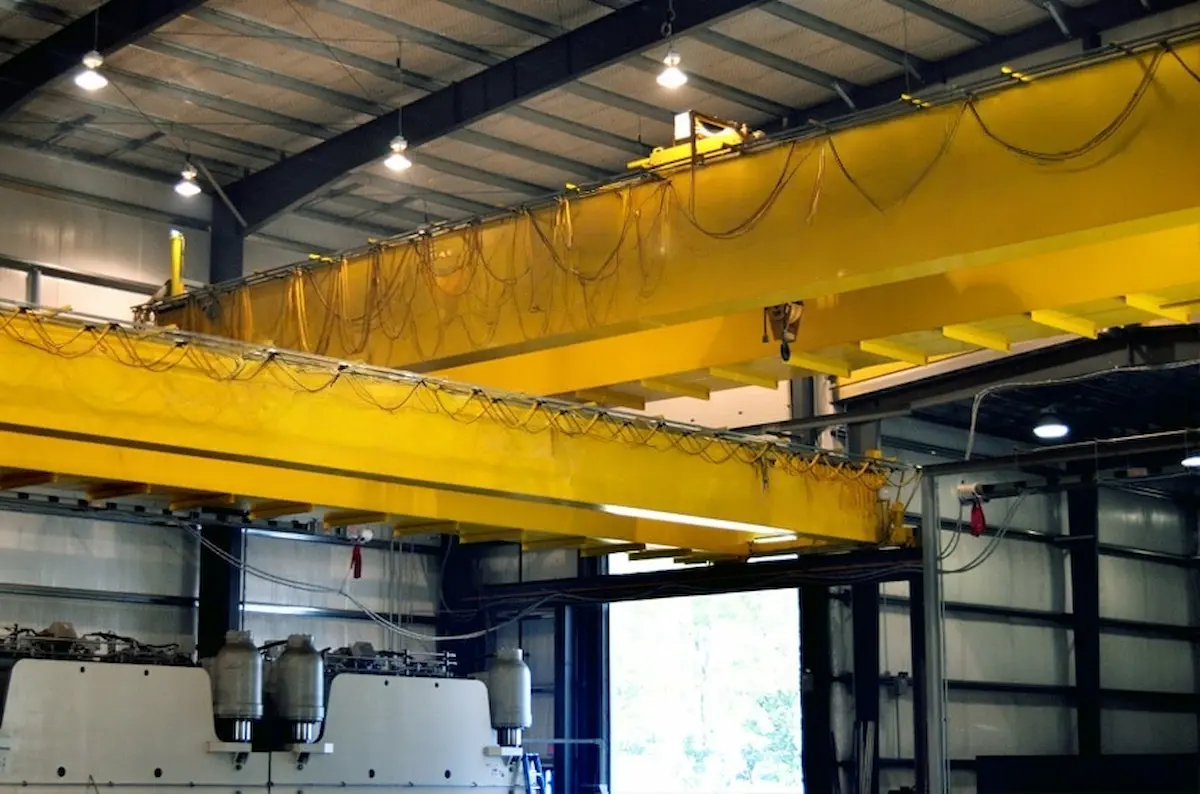
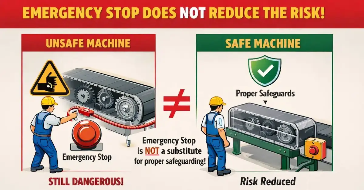
Overhead cranes are widely used in manufacturing, steel metallurgy, port logistics, and modern warehousing. They are key equipment for material handling and heavy lifting. With increasing equipment size and automation, operational risks are also rising. The overhead crane emergency stop system is a core safety function. It can quickly cut off power in emergencies. It also stops equipment operation effectively. This prevents accidents from expanding. Industry accident cases show an important conclusion. Proper emergency stop design and standardized management are essential for personnel and equipment safety.
Analysis of Standards for Overhead Crane Emergency Stop Systems
The design of the overhead crane emergency stop system affects both stability and safety. It directly impacts personnel and property protection. In engineering practice, relevant domestic and international standards must be followed. The system must provide reliable and fast response in emergencies.
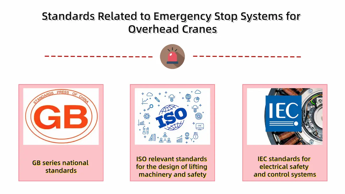
National Standards and Industry Regulations
In the Chinese market, emergency stop design mainly follows GB standards. These include safety regulations and electrical control codes. For export or international projects, global standards must also be met, including:
◉ISO standards for cranes and safety design: These include ISO 4309, ISO 20332, ISO 23814, and ISO 12482. They cover rope maintenance, design verification, inspector competence, and health monitoring.
◉IEC electrical safety and control standards: These include IEC 61508, IEC 62061, IEC 62443, and IEC 60730. They cover functional safety and industrial control requirements.
These standards clearly define emergency stop functions and logic. They also specify circuit structure and testing methods. The system must have highest priority and independent reliability. It must also support fast recovery.
Basic Electrical Safety Design Requirements
The emergency stop system is a key safety control function. Its electrical design should follow these principles:
◉Independence principle: The emergency circuit must be independent from normal control circuits. This prevents PLC or signal failures from causing malfunction.
◉Fail-safe principle: During power loss or component failure, the system enters a safe state automatically.
◉Forced disconnection mechanism: Emergency buttons usually use normally closed contacts. Power is cut immediately after activation.
◉Reliable grounding and insulation protection: This prevents leakage, short circuit, and electrical interference.
Electrical components should use industrial-grade safety relays or safety PLC modules. They must have proper certification. Many high-end clients require PL d or SIL 2. Some projects require PL e or SIL 3 levels.
Emergency Stop Categories and Response Time
According to risk levels, emergency stop functions are typically divided as follows:
◉Category 0 emergency stop: Power is cut immediately. The motor stops by braking. It suits high-risk conditions.
◉Category 1 emergency stop: Controlled deceleration occurs first. Power is cut afterward. It suits sensitive equipment.
Response time is usually required at millisecond level. The control circuit must disconnect quickly. For heavy-duty overhead cranes, mechanical brake response must also be calculated.

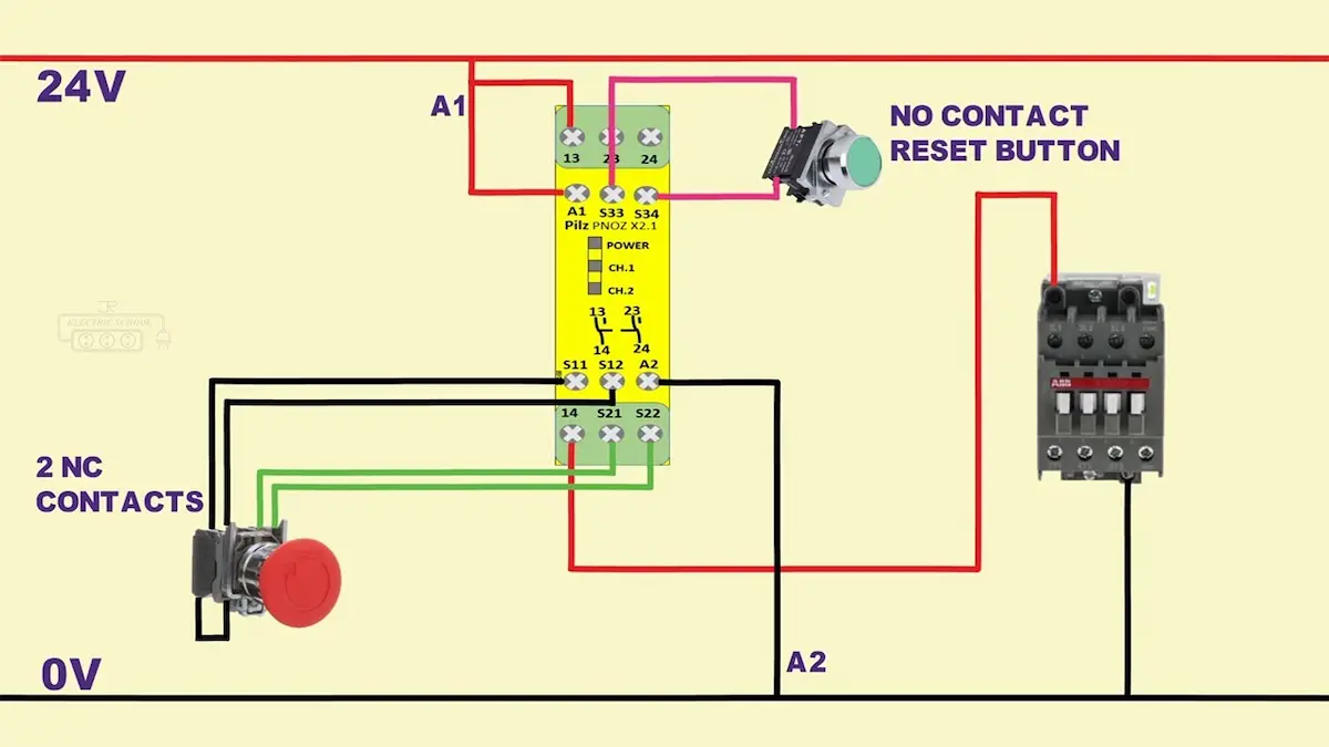
Safety Circuit and Redundancy Principles
To improve reliability, emergency stop systems use dual-channel or multi-channel redundancy. Core principles include:
◉Dual-circuit control structure: Two independent circuits monitor simultaneously. Any abnormality triggers shutdown.
◉Cross-monitoring mechanism: Safety relays monitor circuit status continuously. This prevents contact welding or line break faults.
◉Self-test and fault diagnosis: The system checks circuit integrity at startup.
◉Anti-reset design: After emergency activation, manual reset is required. Automatic restart is prevented.
Through proper standards and redundancy design, safety level improves significantly. This ensures stable overhead crane operation.
Core Design Points of Overhead Crane Emergency Stop Systems
Scientific design is the foundation for efficient and reliable operation. Core design should consider structure and electrical control. Mechanical linkage and ergonomics are also important.
System Structural Design
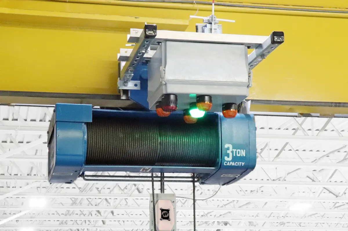
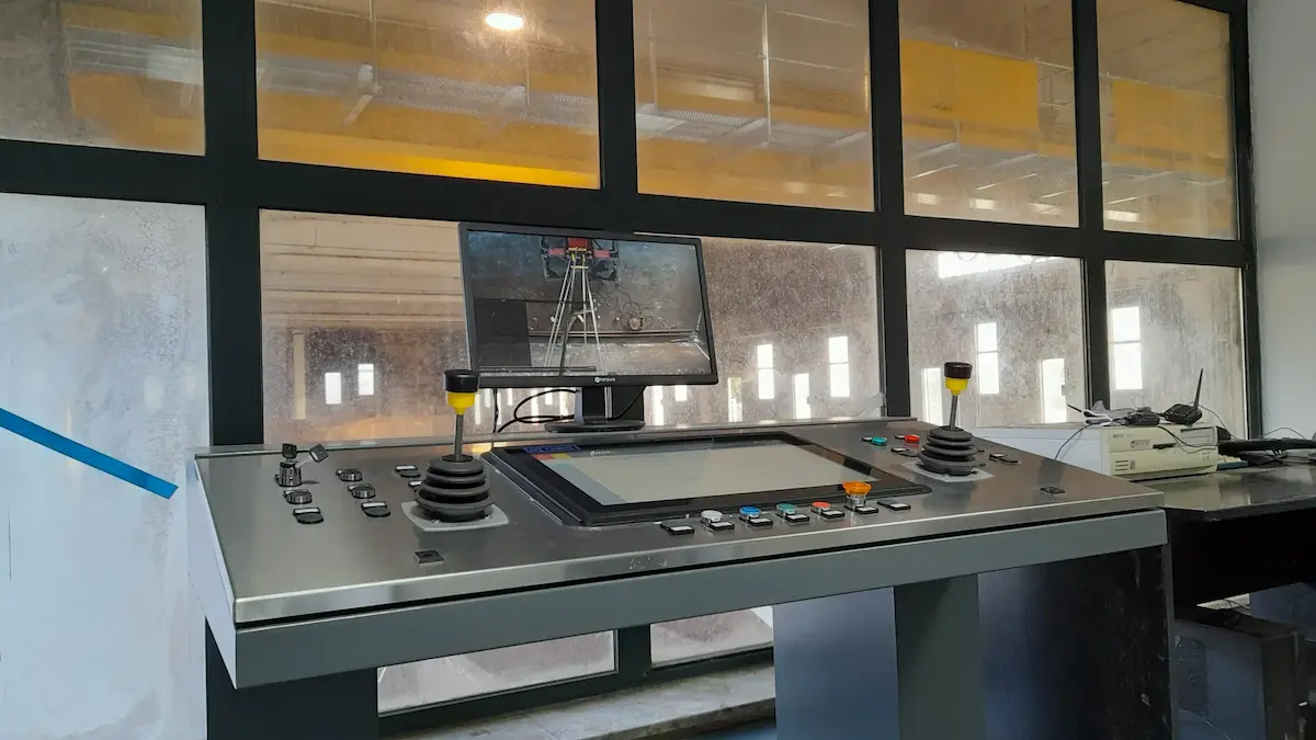
◉Emergency button layout and installation: Buttons must be easy to reach and clearly visible. Locations include cabin, ground stations, and remote receivers. Large or double-girder overhead cranes require multiple emergency buttons.
◉Control circuit logic: The logic must follow emergency priority. When triggered, all motion commands are interrupted immediately. Other control signals are blocked.
◉Main circuit power cutoff: After activation, the main contactor or breaker must disconnect. Motor power stops. The brake system engages simultaneously.
Electrical and Control System Design
◉Safety relay and safety PLC application: Industrial safety relays or safety PLC modules build the system. Safety relays use force-guided contacts. This prevents dangerous contact welding. True fail-safe control is achieved. Signal monitoring and diagnostics are included.
◉Dual-channel redundancy and self-test: Dual inputs provide redundant control. If one channel fails, safe stop remains active. Startup self-test checks wiring and contacts.
◉Anti-misoperation and reset protection: Emergency buttons use mushroom heads with mechanical latching. This prevents accidental triggering or reset. Reset requires manual rotation or pulling.

Mechanical Braking and Linkage Control
◉Electromagnetic brake fast response: The brake engages automatically when power is lost. It ensures rapid stopping of hook and load.
◉Power-loss protection and anti-drop design: Hoisting mechanisms must include reliable brakes and anti-drop devices. This prevents load slipping during faults.
◉Integration with variable frequency systems: In VFD-controlled overhead cranes, the emergency system works with the drive. Output is cut quickly for safe stopping.
◉STO function: Modern cranes widely use VFDs. Direct contactor cutoff may harm the drive. It may also cause load drift. High-end cranes use VFDs with Safe Torque Off. This works together with the emergency stop system.

Human Factors and Operational Safety
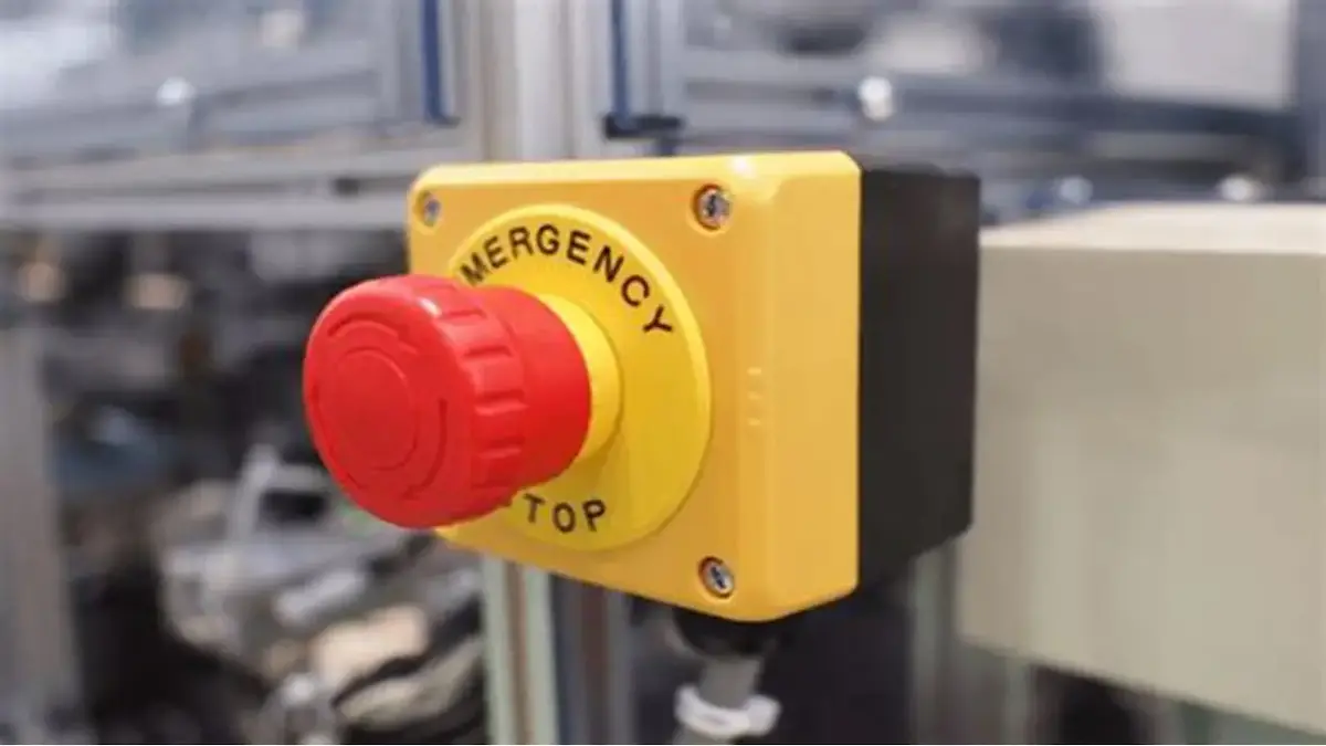
◉Button color and marking: Emergency buttons use red mushroom heads with yellow bases. They follow international safety marking rules.
◉Operational convenience and visibility: Button positions must avoid obstruction. Adequate operating space is required. Markings must be clear and visible.
◉Emergency stop in remote control systems: In wireless control, the emergency function must be an independent safety channel. It must remain reliable even during communication faults.

From Design to Practice: Key Engineering Implementation Points
The overhead crane emergency stop system requires both sound design and strict execution. From early risk assessment to installation and maintenance, a closed-loop control system is essential. Only then can long-term safe and stable operation be ensured.
|
Stage |
Key Content |
Implementation Points |
Control Objective |
| Design Stage | Risk assessment (FMEA analysis) | Identify failures such as button failure, circuit break, contact welding, and brake delay | Eliminate design risks early |
| Risk level evaluation | Score probability, severity, and detectability | Identify high-risk links | |
| Preventive and improvement measures | Apply dual-circuit redundancy, safety relay monitoring, and self-test | Reduce system failure probability | |
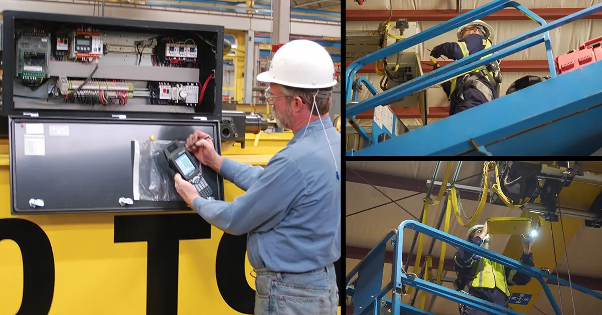
| Installation Stage | Safety circuit wiring | Route safety circuits independently from power cables | Improve system stability |
| Component installation inspection | Check button firmness and safety module installation | Ensure hardware reliability | |
| Commissioning Stage | Functional commissioning | Test main circuit cutoff time and brake response | Verify response speed |
| Multi-scenario testing | Simulate no-load, rated load, and extreme conditions | Ensure reliable stopping | |
| Acceptance Stage | On-site testing | Power cuts immediately after activation with manual reset | Meet standard requirements |
| Acceptance records | Generate test reports and traceability files | Improve quality management | |
| Operation and Maintenance | Periodic functional checks | Regularly test buttons and circuit integrity | Maintain long-term effectiveness |
| Electrical and brake inspection | Check loose terminals, aging wires, and brake wear | Prevent safety hazards | |
| Maintenance records | Record inspection and repair data | Enable lifecycle management |
Through this systematic process, the overhead crane emergency stop system forms a closed-loop control. It greatly improves safety level and operational reliability. It also meets strict industrial safety requirements.
Overhead Crane E-Stop Keeping Tripping? Troubleshooting & Solutions
During actual operation, emergency stop systems may show abnormalities. Causes include environment, control design, or poor maintenance. Proper analysis and optimization improve stability and safety.
Root Cause Analysis of False Emergency Stops
False triggering reduces production efficiency. It also increases mechanical wear from frequent stops. Common causes include:
|
Problem Type |
Main Cause |
Optimization Measure |
| Electrical interference | Power and control cables not separated | Route safety circuits independently with shielding and grounding |
| Contact bouncing | Internal contacts aged or poorly connected | Use industrial high-reliability emergency buttons |
| Loose wiring | Terminal connections not secure | Tighten terminals and perform regular inspection |
| Wireless interference | Unstable remote control signals | Use independent safety channels and anti-interference design |
Optimizing wiring and using high-quality components reduces false trips effectively.
Solutions for Control System Delay
Under heavy load or high speed, response time is critical. If delay occurs, possible causes include:
◉Excessive control logic layers and complex signal paths
◉PLC scan cycle too long
◉Main contactor response lag
◉Brake engagement too slow
Optimization measures include:
◉Use dedicated safety relays or safety PLC modules
◉Simplify control logic and reduce intermediate relays
◉Select fast-response brakes
◉Test and verify key component response times
These actions ensure millisecond-level emergency stopping.
Optimized Design for Harsh Environments
In steel plants, foundries, or ports, harsh conditions require stronger design.
High-temperature optimization:
◉Use high-temperature-resistant electrical components
◉Install thermal insulation enclosures
◉Improve ventilation and heat dissipation
High-dust optimization:
◉Use high protection level equipment, such as IP65 or higher
◉Enhance sealing structure design
◉Clean dust inside control cabinets regularly
High-humidity or corrosive optimization:
◉Apply anti-corrosion coatings and stainless structures
◉Strengthen grounding and insulation protection
Environmental adaptation significantly improves reliability and service life.

Trends in Intelligence and Remote Monitoring
With industrial digitalization, overhead crane emergency stop systems are becoming smarter. Main trends include:
◉Introduce intelligent PLC for real-time status monitoring
◉Connect to industrial IoT platforms for remote circuit monitoring
◉Automatically record emergency stop events for traceability
◉Use data analytics to predict faults and enable preventive maintenance
Intelligent upgrades improve safety management. They also reduce downtime costs and optimize equipment maintenance.
HSCRANE Overhead Crane Emergency Stop System Advantages
◉Compliance with international safety standards: HSCRANE emergency stop systems comply with ISO, FEM, and EN requirements. Design and validation strictly follow required safety levels and control categories. This ensures global compliance and operational safety.
◉Highly reliable safety control system: Industrial-grade safety relays or safety PLC modules are adopted. A dual-channel redundant structure ensures millisecond-level response. HSCRANE uses safety relays with forcibly guided contacts. The circuit achieves SIL 2 / PL d safety level. The system features fail-safe design and self-diagnostic functions. It prevents single-point failures from causing safety loss. Stable operation under heavy-duty conditions is ensured.
◉Customized solution capability: HSCRANE provides tailored emergency stop designs for different tonnages and spans. Solutions also consider duty class and site environments. Typical environments include high temperature, dust, and corrosion. Integration with variable frequency control and remote monitoring is supported. The system meets multi-industry application requirements.
◉Comprehensive technical support and after-sales service: HSCRANE provides full-process technical support. Support covers design, installation, commissioning, and site acceptance. Regular inspection and remote guidance mechanisms are established. The emergency stop system maintains high safety throughout its lifecycle.

Future Trend: Intelligent Safety and Digital Upgrade
In the future, overhead crane emergency stop systems will become more intelligent. Digital development is also accelerating across the industry. Safety PLC combined with Industrial Internet of Things enables data connectivity. System status and emergency records can be uploaded in real time. Fault information is also transmitted to the monitoring platform. This enables remote monitoring and maintenance management. Real-time diagnostics can quickly identify abnormal circuits. It can also detect contact aging and brake delay problems. Troubleshooting time is significantly reduced. Unplanned downtime risk is also lowered. Data-driven safety management enables operation data analysis. Maintenance cycles and predictive strategies can be optimized. Maintenance shifts from reactive repair to preventive action. Overall equipment safety and management efficiency are improved. This provides reliable support for industrial safety production.

The overhead crane emergency stop system is the core safety barrier. It protects both equipment operation and personnel safety. Every stage directly affects reliability and response efficiency. These stages include standards, design, implementation, and maintenance. By adopting redundant safety circuits and fast braking mechanisms, safety improves. Intelligent monitoring technologies further enhance system reliability. Enterprises can effectively reduce failure risks and downtime costs.
If you are planning a new project or system upgrade, contact HSCRANE. We will provide higher-standard safety protection for your equipment.
Want to learn the core control technology behind emergency stop systems?
Click How PLC Control systems Improve Crane Operating Efficiency and Safety. Explore PLC applications and optimization in crane safety. Master intelligent management and rapid response solutions.
FAQ
Q1: Is an emergency stop system mandatory for overhead cranes?
A1: Yes. According to relevant safety standards, overhead cranes must include emergency stop devices. They allow rapid power cutoff during emergencies. This protects personnel and equipment.
Q2: Where should emergency stop buttons be installed?
A2: They are usually installed in the cabin and ground control station. They are also installed on wireless remote controllers. Operators must access emergency stop from any critical position.
Q3: What is the typical response time of an emergency stop system?
A3: With proper design, electrical response reaches millisecond level. Total stopping time depends on brake action performance. Comprehensive evaluation is required.
Q4: Why is dual-channel redundancy required for emergency stop systems?
A4: Dual channels prevent failure caused by a single fault. They significantly improve the safety level. If one channel fails, the other ensures safe stopping.
Q5: Can the system automatically restart after emergency stop activation?
A5: No. Standards require manual reset confirmation. This prevents unintended automatic restart.
Q6: How to ensure reliability in high temperature or dusty environments?
A6: Select electrical components with high protection ratings. Strengthen sealing design where necessary. Regularly inspect terminals and brake performance. This ensures stable operation in harsh conditions.
Q7: Can the emergency stop system connect to remote monitoring platforms?
A7: Yes. Safety PLC combined with Industrial Internet of Things enables connectivity. Emergency status monitoring and fault logging become possible. Remote diagnostics improves maintenance efficiency and safety management.
Q8: Can I upgrade an old crane’s emergency stop system to meet current IEC standards?
A8: Yes. HSCRANE provides Safety Retrofit Kits that upgrade single-channel systems to dual-channel redundancy, integrating modern safety relays and STO-compatible VFDs without replacing the entire crane.
This document is for reference only. Specific operations must strictly comply with local laws and regulations and equipment manuals.